

Int J Performability Eng ›› 2018, Vol. 14 ›› Issue (12): 2927-2940.doi: 10.23940/ijpe.18.12.p3.29272940
Previous Articles Next Articles
Risu Na, Haifeng Zhai( ), and Haitang Cen
Revised on
;
Accepted on
Contact:
Zhai Haifeng
E-mail:nrs3000@163.com
Risu Na, Haifeng Zhai, and Haitang Cen. Layer Design and Fluid-Solid Coupling Analysis of the Thermoplastic Composite Wind Turbine Blade [J]. Int J Performability Eng, 2018, 14(12): 2927-2940.
Add to citation manager EndNote|Reference Manager|ProCite|BibTeX|RefWorks
Table 1
Performance parameters of blade materials"
| Material | Elastic modulus | Shear modulus | Poisson ratio | Density |
|---|---|---|---|---|
| Unit | Gpa | Gpa | - | kg/m3 |
| A | E1=72.45 | G12=2.21 | v21=0.29 | 1440 |
| E2=7.42 | G13=2.21 | v31=0.29 | ||
| E3=7.42 | G23=2.09 | v23=0.28 | ||
| B | E1=22.83 | G12=12.80 | v21=0.62 | 1513 |
| E2=20.30 | G13=12.80 | v31=0.62 | ||
| E3=18.30 | G23=11.32 | v23=0.51 | ||
| C | E1=55.96 | G12=18.68 | v21=0.41 | 1513 |
| E2=31.48 | G13=17.29 | v31=0.41 | ||
| E3=23.95 | G23=16.54 | v23=0.35 | ||
| E | 3.44 | 1.38 | 0.3 | 1235 |
| F | 3.50 | 1.40 | 0.3 | 1100 |
| G | 0.26 | 0.02 | 0.3 | 200 |

Figure 1
Three-dimensional equivalent volume element model"
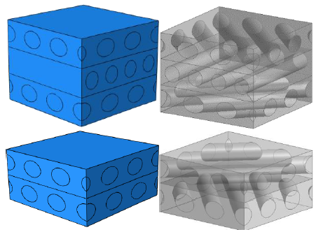
Figure 2
Deformed cloud chart of triaxial cloth [±45]4[0]2"
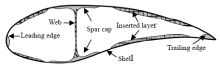
Figure 3
Schematic diagram of wind turbine blade chord structure"


Figure 4
The layer distribution of the spar cap along the spreading direction"
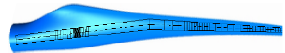
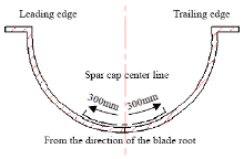
Figure 5
The laying scheme of the spar cap width"
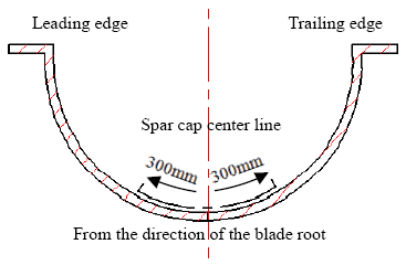
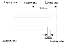
Figure 6
Staggered laying scheme of the spar cap"
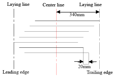
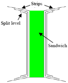
Figure 7
Symmetrical structure layers scheme design of the web and sandwich"

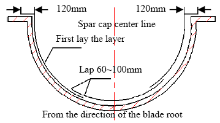
Figure 8
The overlap layers designed schemes of the shell"
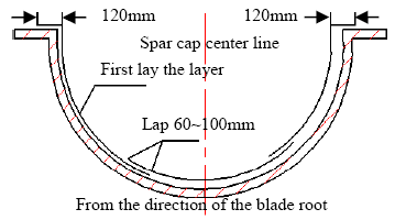

Figure 9
Laying schemes of core material"

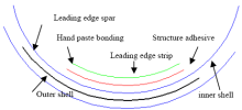
Figure 10
Laying schemes of leading edge spars"
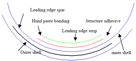

Figure 11
The thickness distribution of s-shaped cross layer on the trailing edge"
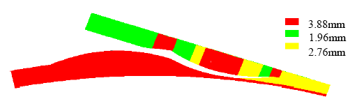

Figure 12
Design scheme range of trailing edge spars along the spread"
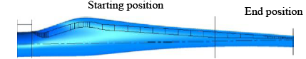
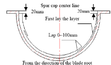
Figure 13
Laying schemes of blade root reinforcement layer"
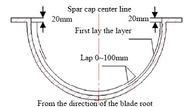
Table 2
Properties of glass fiber composites"
| Materials | E1 | E2 | Gxy | Vxy | Density |
|---|---|---|---|---|---|
| Unit | GPa | GPa | GPa | - | kg/m3 |
| A | 41.8 | 14.00 | 2.63 | 0.28 | 1920 |
| B | 13.6 | 13.3 | 11.80 | 0.51 | 1780 |
| C | 27.7 | 13.65 | 7.20 | 0.39 | 1850 |
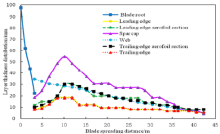
Figure 14
The thickness distribution of the blade each part along the span direction"
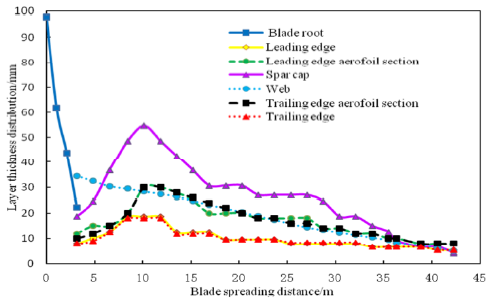
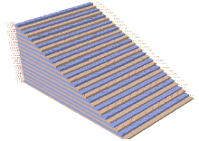
Figure 15
The structure diagram of the blade layer"
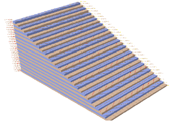
Table 3
Complete layer design scheme of blade"
| r/R | Blade root | Leading edge | Leading edge aerofoilsection | Spar cap | Web | Trailing edge aerofoil section | Trailing edge |
|---|---|---|---|---|---|---|---|
| 0.000 | 1E+2B+48C+2D+2F | - | - | - | - | - | - |
| 0.025 | 1E+2B+28C+2D+2F | - | - | - | - | - | - |
| 0.050 | 1E+2B+18C+2D+2F | - | - | - | - | - | - |
| 0.075 | 1E+2B+4C+6A+2F | 1E+2B+2F | 1E+2B+1C+1A+G+2F | 1E+2B+4C+3A+2F | 6B+G | 1E+2B+1A+G+2F | 1E+2B+2F |
| 0.115 | - | 1E+2B+2A+2F | 1E+2B+1C+2A+G+2F | 1E+2B+2C+11A+2F | 6B+G | 1E+2B+1C+1A+G+2F | 1E+2B+1A+2F |
| 0.155 | - | 1E+2B+2C+1A+2F | 1E+2B+1C+2A+G+2F | 1E+2B+2C+21A+2F | 6B+G | 1E+2B+1C+2A+G+2F | 1E+2B+2C+1A+2F |
| 0.200 | - | 1E+2B+2C+6A+2F | 1E+2B+2C+2A+G+2F | 1E+2B+2C+31A+2F | 8B+G | 1E+2B+2C+2A+G+2F | 1E+2B+1C+9A |
| 0.240 | - | 1E+2B+2C+6A+2F | 1E+2B+2C+6A+G+2F | 1E+2B+2C+36A+2F | 8B+G | 1E+2B+2C+6A+G+2F | 1E+2B+1C+9A |
| 0.280 | - | 1E+2B+2C+6A+2F | 1E+2B+2C+6A+G+2F | 1E+2B+2C+31A+2F | 8B+G | 1E+2B+2C+6A+G+2F | 1E+2B+1C+9A |
| 0.320 | - | 1E+2B+2C+1A+2F | 1E+2B+2C+5A+G+2F | 1E+2B+2C+26A+2F | 8B+G | 1E+2B+2C+5A+G+2F | 1E+2B+1C+4A |
| 0.360 | - | 1E+2B+2C+1A+2F | 1E+2B+2C+4A+G+2F | 1E+2B+2C+21A+2F | 6B+G | 1E+2B+2C+4A+G+2F | 1E+2B+1C+4A |
| 0.400 | - | 1E+2B+2C+1A+2F | 1E+2B+2C+2A+G+2F | 1E+2B+2C+16A+2F | 6B+G | 1E+2B+2C+3A+G+2F | 1E+2B+1C+4A |
| 0.440 | - | 1E+2B+1A+2F | 1E+2B+2C+2A+G+2F | 1E+2B+2C+16A+2F | 6B+G | 1E+2B+2C+2A+G+2F | 1E+2B+1C+2A |
| 0.480 | - | 1E+2B+1A+2F | 1E+2B+2C+2A+G+2F | 1E+2B+2C+16A+2F | 6B+G | 1E+2B+2C+2A+G+2F | 1E+2B+1C+2A |
| 0.520 | - | 1E+2B+1A+2F | 1E+2B+2C+1A+G+2F | 1E+2B+2C+13A+2F | 6B+G | 1E+2B+2C+1A+G+2F | 1E+2B+1C+2A |
| 0.560 | - | 1E+2B+1A+2F | 1E+2B+2C+1A+G+2F | 1E+2B+2C+13A+2F | 6B+G | 1E+2B+2C+1A+G+2F | 1E+2B+1C+2A |
| 0.600 | - | 1E+2B+2F | 1E+2B+2C+1A+G+2F | 1E+2B+2C+13A+2F | 6B+G | 1E+2B+2C+1A+G+2F | 1E+2B+1C+1A |
| 0.640 | - | 1E+2B+2F | 1E+2B+2C+1A+G+2F | 1E+2B+2C+13A+2F | 6B+G | 1E+2B+2C+1A+G+2F | 1E+2B+1C+1A |
| 0.680 | - | 1E+2B+2F | 1E+2B+1C+1A+G+2F | 1E+2B+2C+11A+2F | 4B+G | 1E+2B+1C+1A+G+2F | 1E+2B+1C+1A |
| 0.720 | - | 1E+2B+2F | 1E+2B+1C+1A+G+2F | 1E+2B+2C+6A+2F | 4B+G | 1E+2B+1C+1A+G+2F | 1E+2B+1C+1A |
| 0.760 | - | 1E+2B+2F | 1E+2B+1C+1A+G+2F | 1E+2B+2C+6A+2F | 4B+G | 1E+2B+1C+1A+G+2F | 1E+2B+1C+1A |
| 0.800 | - | 1E+1B+1A+2F | 1E+2B+1C+1A+G+2F | 1E+2B+2C+3A+2F | 4B+G | 1E+2B+1C+1A+G+2F | 1E+2B+1A |
| 0.840 | - | 1E+1B+1A+2F | 1E+2B+1A+G+2F | 1E+2B+2C+1A+2F | 4B+G | 1E+2B+1A+G+2F | 1E+2B+1A |
| 0.860 | - | 1E+1B+1A+2F | 1E+2B+1A+G+2F | 1E+2B+1A+2F | 2B+G | 1E+2B+1A+G+2F | 1E+2B+1A |
| 0.920 | - | 1E+1B+1A+2F | 1E+2B+2F | 1E+3A+2F | 2B+G | 1E+2B+2F | 1E+2B+1A |
| 0.960 | - | 1E+1B+2F | 1E+2B+2F | 1E+3A+2F | 2B+G | 1E+2B+2F | 1E+2B |
| 1.000 | - | 1E+1B+2F | 1E+2B+2F | 1E+1A+2F | 2B+G | 1E+2B+2F | 1E+2B |

Figure 16
The design of the complete blade layer"
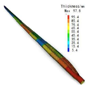
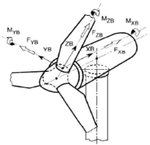
Figure 17
Reference coordinate of load calculation"
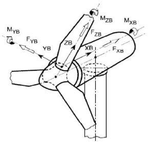
Table 4
Classification of wind turbine blade load types"
 |
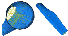
Figure 18
Loading method of MPC coupling constraint"


Figure 19
Periodic boundary condition"
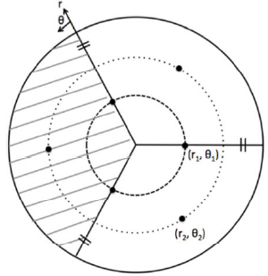
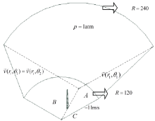
Figure 20
Divideof fluid domain"
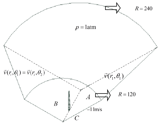
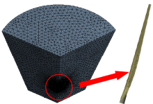
Figure 21
Meshing divide of fluid domain"
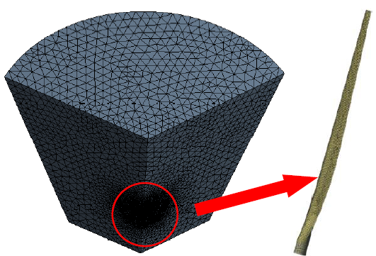
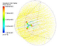
Figure 22
Velocity flow diagram around the blade"
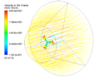
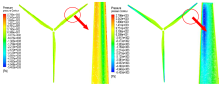
Figure 23
The surface pressure distribution of blades windward and leeward surface"

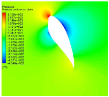
Figure 24
The maximum chord length plane pressure contour"


Figure 25
The velocity vector on the maximum chord length plane"
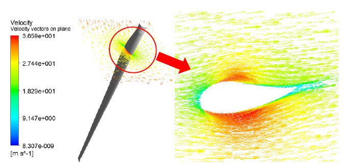
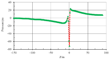
Figure 26
Pressure changes along the Z axis"
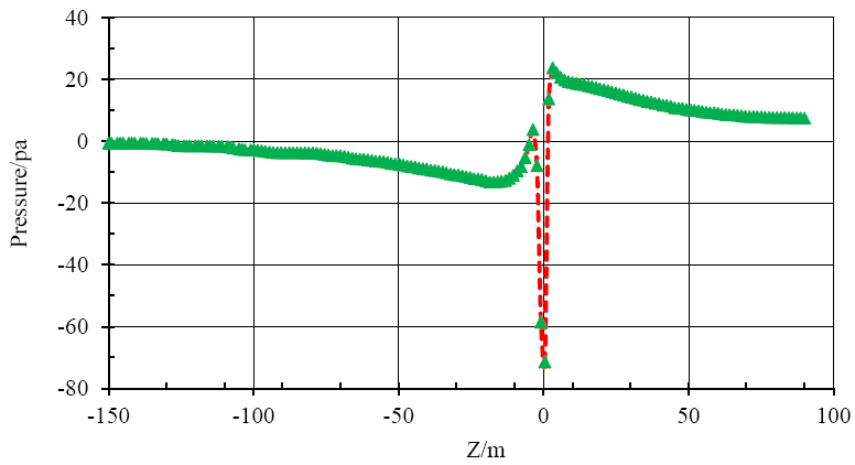
Table 5
Error comparison between two loading methods with the force and torque results in the root of GH blade"
| Loading mode | FXB/kN | FYB/kN | FZB/kN | MXB/(N·m) | MYB/(N·m) | MZB/(N·m) |
|---|---|---|---|---|---|---|
| Error | 4.04% | -1.54% | 0.29% | 2.07% | -2.54% | -0.82% |
| MPC | 1250.71 | -144.34 | 1580.83 | 2.42×10⁶ | 3.15×10⁵ | 6.11×10³ |
| GHBlade | 1200.21 | -146.56 | 1576.30 | 2.37×10⁶ | 3.23×10⁵ | 6.16×10³ |
| Distribution force | 1210.43 | -147.29 | 1578.10 | 2.40×10⁶ | 3.31×10⁵ | 6.15×10³ |
| Error | 0.84% | 0.50% | 0.11% | 1.25% | 2.42% | -0.16% |
| [1] | K. Larsen , “Recycling Wind Turbine Blades,” Renewable Energy Focus,Vol. 9, No. 7, pp. 70-73, 2009 |
| [2] |
S. T. Bashir, L. Yang, J. J. Liggat , “Kinetics of Dissolution of Glass Fibre in Hot Alkaline Solution,” Journal of Materials Science,Vol. 53, No. 3, pp. 1710-1722, 2018
doi: 10.1007/s10853-017-1627-z |
| [3] |
K. T. Ramirez, D. A. Turcotte, S. Pike , “Unsustainable Wind Turbine Blade Disposal Practices in the United States,” New Solutions A Journal of Environmental & Occupational Health Policy Ns, Vol. 26, No. 4,pp. 582-588, 2017
doi: 10.1177/1048291116676098 pmid: 27794074 |
| [4] | C. L. Li, J. H. Wang, Z. M. Xue , “Application and Development of Materials of Large-Scale Wind Turbine Blades,” Fiber Reinforced Plastics, No. 4, pp. 49-52, 2008 |
| [5] | W. Y. Meng, P. W. Sun, L. T. Zhang , “Research and Application of Property Equivalence Algorithm for Composite Lamination Plate based on Energy Method,” Acta Energiae Solaris Sinica, Vol. 35, No. 8, pp. 1505-1510, 2014 |
| [6] |
D.O. Yu and O. J. Kwon , “Predicting Wind Turbine Blade Loads and Aeroelastic Response Using a Coupled CFD-CSD Method,” Renewable Energy, Vol. 70, pp. 184-196, 2014
doi: 10.1016/j.renene.2014.03.033 |
| [7] | F. D. Bianchi, H. D. Battista, R. J. Mantz , “The Wind and Wind Turbines,” Springer, Berlin, 2007 |
| [8] | D.J. Oehlers and R. Seracino , “Design of FRP and Steel Plated RC Structures: Retrofitting Beams and slabs for Strength,” Stiffness and Ductility, Elsevier, Netherlands, 2004 |
| [9] |
L.C. Forcier and S. Joncas , “Development of a Structural Optimization Strategy for the Design of Next Generation Large Thermoplastic Wind Turbine Blades,” Structural & Multidisciplinary Optimization,Vol. 45, No. 6, pp. 889-906, 2012
doi: 10.1007/s00158-011-0722-z |
| [10] |
A. P. Vassilopoulos, B. D. Manshadi, T. Keller , “Influence of the Constant Life Diagram Equationtion on the Fatigue Life Prediction of Composite Materials,” International Journal of Fatigue,Vol. 32, No. 4, pp. 659-669, 2010
doi: 10.1016/j.ijfatigue.2009.09.008 |
| [11] | J. X. Li, Z. M. Xue, J. H. Wang, B. C. Feng , “Development Status and Trend of Large-Scale Wind Turbine Rotor Blade,” Fiber Reinforced Plastics/Composites, Vol. 4, pp. 49-52, 2008 |
| [12] | M. Hansen , “Aerodynamics of Wind Turbines,” Weltbild, Augsburg, 2008 |
| [13] | H. Li and T. G. Wang , “FEM Simulation of Distributed Force Function Loading Applied on Wind Turbine Blade,” Acta Energiae Solaris Sinica,Vol. 34, No. 3, pp. 485-489, 2013 |
| No related articles found! |
|
||